Creating the shader
Values
When you’re creating shaders, you’re doing math. There’s no getting around it. Creating shaders, whether you’re coding them or using nodes, is throwing calculations onto numbers.
Let’s focus on colors for now. Each pixel on your screen has a color and each color is build from R, B, G and A. In shaders, these values range from 0 to 1. If you think about the texture we just created, you can see that it has a red channel with values ranging from 0 to 1 depending on the position of the pixel. It’s the same case with the green channel. However, the blue channel has only values of 0. We’re not using an alpha channel in this texture, but if it had one, it would contain only values of 1 which means there’s no transparency. So, if you would take the red channel and put it into the Base Color of your shader, you would get a grayscale result. Let’s test it.
STEP 9
Create a new material and call it something like “Clouds”. Then open it. You’ll see an empty material canvas apart from the result node of the material.
STEP 10
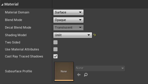
In the material panel (generally on the left) you have your material settings. Change the Shading Model to Unlit, so the geometry you’ll be using won’t pickup any light.
STEP 11
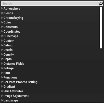
Right-click on the canvas. A search window should pop up. This is where you can find all the nodes you’ll be needing.
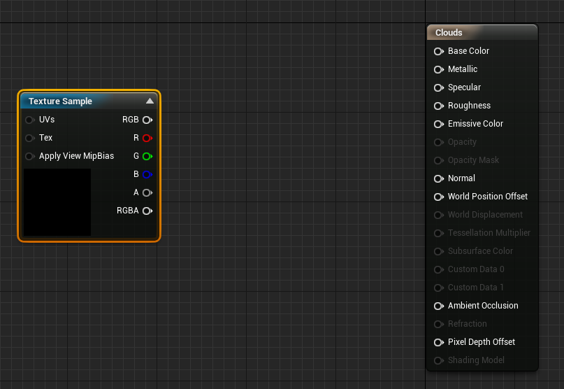
Type “Texture Sample” and press enter or click on the canvas while pressing ‘T’.
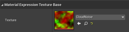
In the details panel of the Texture Sample node, add the texture you just created.
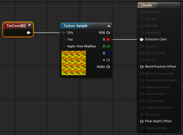
Connect the R (red) output of the Texture Sample node to the Emissive Color of your material.
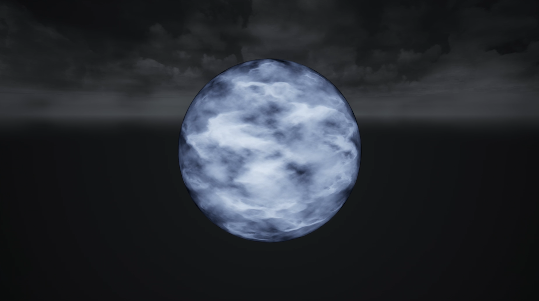
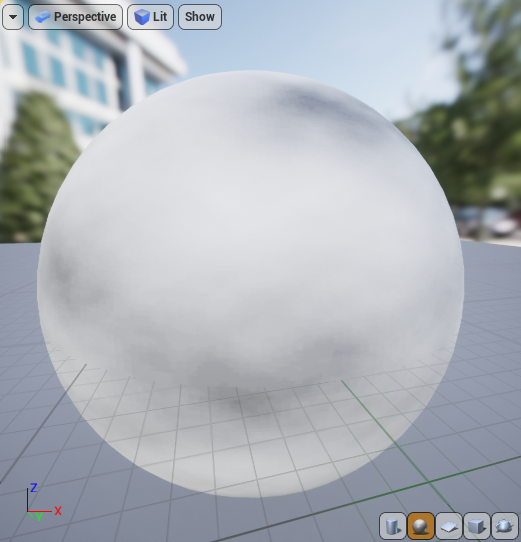
Your preview window will probably looks similar to the image on the left.
UV’s
In shaders, you can determine how to lay out a texture over your UV’s. You can for example tile your texture, offset it or scale it up. We are going to tile our texture across the UV’s of the sphere.
STEP 12
Right-click, type “TextureCoordinate” or click on the canvas while pressing ‘U’ and press enter. Connect this to the UV’s of the Texture Sample node.
In the details panel, change the UTiling and VTiling both to 4. This way we’ll tile our texture four times horizontally and vertically. If you’re not satisfied with how it looks, try a tiling it a little more or less.
Parallax
Right now we have the beginning of something that’s supposed to look like clouds, but it’s very flat. Let’s solve that problem by adding some bump offset or ‘parallax’ effect to it.
STEP 12
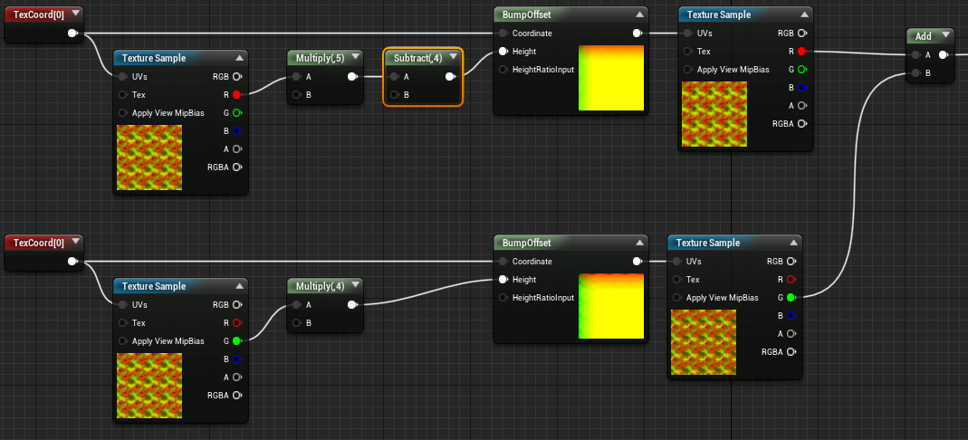
Get a “Bump Offset” node the same way you’ve been adding nodes to the canvas in previous steps. Take the output from the TexCoord node and add it to the Coordinate input of the BumpOffset node. Copy the Texture Sample you already have and also input the TexCoord node into the ‘UV’s’ input of that node. Then take the red channel and attach it to a multiply node. Connect the output of this to the ‘Height’ input of the BumpOffset node. Please check out the image below for the correct setup.

If you click on the Multiply node, you can change the scalar that the texture will be multiplied with in the details panel. Don’t go overboard with this. A value between 1 and 6 should suffice for this particular shader. I went with 5. If you multiply it too much, you’ll get unrealistic results.
Try moving around the camera around the object in your shader preview window. It already looks way less flat, doesn’t it?
STEP 13
We’re going to make it more interesting by adding another layer of clouds. This is where we’ll be using the second texture we created.
Copy all the nodes on the canvas and paste them underneath. Then right click on the canvas and type “Add” or click on the canvas while pressing ‘A’. Drag the R output from the first Texture Sample node to the first input of the Add node and the G output from the second Texture Sample node to the second input of the Add node like in the example below. I colored the lines for better visibility of what is going on. Then attach the Add node to the Emissive Color.

STEP 14
It’s fairly hard to make a distinction between different clouds. That’s why we’re going to create a little more depth. We’ll do this by adding one simple node.
Right click on the canvas and type “Subtract”. Then place the node between the first Multiply and Bump Offset node like in the example below. By doing this, we’ll place the first layer of clouds a little more to the background. I went with a value of 4. You can fill this in in the Details panel.
You can play around with different values for the amount of depth you want in the Multiply and Subtract nodes until you’re satisfied with the result!